DELPHI Compact Models
DELPHI Compact Models in FloTHERM PACK
A two-resistor model derived using the JEDEC recommended experimental standards has been shown (ref 1) to give a worst case error in junction temperature of the order of 30%. This is a major improvement over single resistor metrics, and makes a two-resistor model (see "Two-Resistor Compact Models") useful for what-if? type analyses to capture trends.
However, a better solution would be a so-called Boundary Condition Independent (BCI) compact model. The junction temperature from a BCI model, by definition, agrees with that predicted by the detailed model to within engineering accuracy for any boundary condition that could be reasonably encountered in electronics environments. In this sense, the BCI concept is very much a practical definition rather than a strict theoretical one.
In reality, boundary condition independence is not an absolute concept, but rather a relative one. A strict BCI model would give zero predictive errors for any boundary condition - an impossible ideal, especially considering the fact that the experimental data itself is subject to error. Hence it is preferable to speak of models that possess a certain degree of boundary condition independence, or BCI index. The industry standards organization, JEDEC, is currently working on an approach to define this index more precisely.
DELPHI compact models produce a high BCI Index to the extent that these models are useful for predictive work in application-specific environments. In terms of a practical measure, properly derived DELPHI compact models promise a better than 10% accuracy in predicting junction temperatures (when compared to detailed model simulations under identical conditions.) Neither test-based thermal metrics nor two-resistor compact models satisfy this criterion. In addition, an error estimate is an inherent part of the DELPHI method for the generation of a compact model. This makes these models highly useful for sophisticated design work.
Theoretical Basis of DELPHI Compact Models
Project DELPHI
Project DELPHI was a 3-year EU-funded research project, undertaken by a consortium of electronics companies, that concluded in 1996. Its contributions and conclusions have been documented in a number of publications available in the public domain.
The key goals of the project were as follows:
- Define the areas of responsibility that belong to the suppliers (IC part manufacturers) and end-users (system designers) that enables a supply chain
- Enhance our understanding for constructing detailed models of IC packages
- Propose a validated methodology for the creation of BCI compact models of IC packages
An important recommendation of the project was that suppliers take over responsibility for characterizing packages and supplying thermal compact models to end-users. It would then be the responsibility of the end-users to define the boundary conditions specific to their system or application. In other words, once the supplier has created a compact model and supplied it to the end-user, they no longer have the responsibility of qualifying the model under the application-specific environments of their customers; the customers themselves are now empowered to take on the task.
DELPHI Methodology
The key requirement to fulfil the Project DELPHI vision is the availability of a widely accepted standard methodology for the generation of high-accuracy compact models. Project DELPHI proposed a methodology shown in Figure 6-10.
Figure 6-10.
The DELPHI Methodology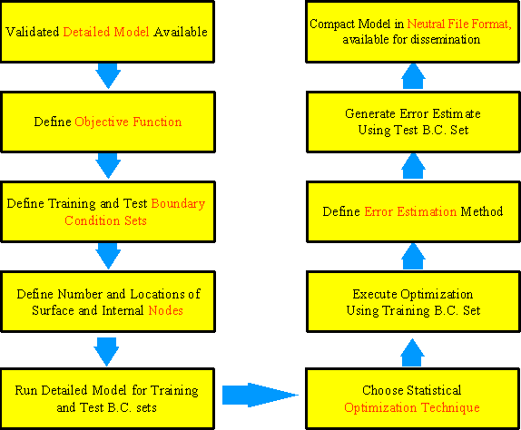
The methodology assumes that an experimentally validated detailed model is available. The detailed model is then simulated under a predefined set of training boundary conditions, expressed in terms of sets of heat transfer coefficients. The set is representative of the wide range of environments that are encountered in electronics cooling. One of the goals of the project was to find a suitably representative set of boundary conditions that encompasses various kinds of electronics cooling environments, such as forced convection, free convection, heatsink, and so on.
Once the environments are defined, the detailed model outer surface is partitioned into a limited number of surface nodes. The process of definition of nodes is a critical part of the DELPHI methodology. This is because it is important for the compact model to interact with its environment as identically as possible to the detailed model. This implies that the surface areas representing nodes of the compact model have a one-to-one correspondence with their corresponding areas in the detailed model. In other words, temperatures over discrete areas on the package (detailed model) surface are each represented by a single averaged nodal value in the compact model.
Figure 6-11.
Possible Node Topology for a PQFP Package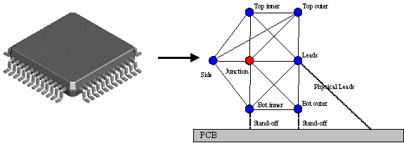
Because the package surface is usually significantly non-isothermal, it is important to sub-divide the package surface into several surface nodes. This is especially important when temperature gradients on a surface are particularly steep, as, for example, in the case of overmolded plastic packages.
Figure 6-12.
Partitioning the Top Surface of a QFP into Two Surface Nodes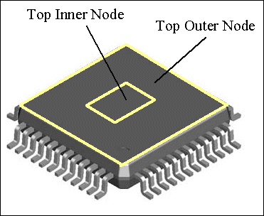
In a large majority of cases, two surface nodes each on the top and bottom surfaces of the package provide sufficient granularity to resolve the temperature gradients. Figure 6-12 illustrates the partitioning of the top surface of a QFP package into two nodes: inner and outer. A similar approach can be adopted for the bottom surface. It is important to note that the relative extent of the inner and outer nodes can affect the quality of the model.
Next, the detailed model is simulated under the assigned boundary condition set, resulting in a large amount of data for heat fluxes and temperatures at various nodes. Next, an objective function is defined. This objective function essentially represents the error in the compact model as compared to the detailed model. Minimization of the objective function can be expected to yield the most accurate compact model.
The objective function in this methodology is defined as the discrepancy between the detailed model and prediction from the compact network summed over both the training boundary condition set (see below) and a finite number of points of interest within the package. In effect, the objective function is the measure of the deviation of the compact model results from the detailed model results. Minimizing the objective function should result in a compact model with a low error.
An acceptable objective function can be constructed in several ways. However, it is strongly recommended that it includes terms related to the heat flux from all the surface nodes and the rise in junction temperature. Although predicting the junction temperature is important to determine whether the package will meet performance criteria, the heat flux is also important as it influences the board temperature and the temperatures in neighboring components. Thus, an objective function that reflects the contribution of both will yield improved compact models.
A recommended formulation of the objective function is:
where:
|
F |
is the objective function |
|
M |
is the number of boundary condition sets |
|
W |
is the weight factor (varying between 0 and 1)1 |
|
N |
is the number of external nodes (inner and outer nodes treated separately) |
|
TJ,C |
is the junction temperature of the compact model |
|
TJ,D |
is the junction temperature of the detailed model |
|
TAmb |
is the ambient temperature |
|
qi,C |
is the flux leaving the node ith in the compact model |
|
qi,D |
is the flux leaving the node ith in the detailed model |
|
Q |
is the total power applied to the junction |
1The weight factor, W, represents the relative weighting given to the junction temperature term as compared to the flux term in the cost function. Thus assigning a value of 1 to W means that only the junction temperature discrepancies are minimized in the objective function, while a value of 0 implies that only the flux terms are taken into account. An intermediate value would indicate the extent to which each of the terms is weighted. A commonly used value is 0.5, which tends to balance the flux and temperature terms. The dependence of the model quality on W can be examined by plotting the error in junction temperatures and fluxes against W.
The thermal resistors in the compact model network are derived by minimizing the objective function using an appropriate optimization scheme. Thus, an optimum compact model network is obtained.
Finally, an error estimate of the compact model is generated by subjecting the network to a test boundary condition set. The test BC set can be the same or different from the training BC set. This error estimate gives feedback about the quality of the compact model.
The network can then be implemented in the relevant thermal analysis tool, whether a simple network solver, a board-level conduction-type tool, or a fully-fledged CFD tool.
Generating DELPHI Compact Models
Salient Points
The FloTHERM PACK implementation closely follows the methodology proposed by Project DELPHI, however, the following additional points should be noted:
- The detailed model used for generating the compact model is the one that would be consistent with the modeling choices selected by the user in the Modeling Choices section of the design sheet. In other words, changing these choices in the design sheet changes the compact model, such that the network is always derived from the selected detailed model.
- Two optimization techniques are offered - the more traditional Linear Least Squares (LLS) method and a state-of-the-art non-linear DOTCOMP™ method. The LLS method is faster and sometimes more robust, but it is not guaranteed to generate the most accurate compact model possible. The DOTCOMP™ method is computationally intensive but almost always yields a compact model with a significantly lower error estimate. (See "Optimization Method" for optimization technique menu details.)
- The boundary condition set used for optimization is the 44 set for area array packages and the 88 set (44X2) for leaded packages. The 44 set is extracted from the 99 set proposed by the DELPHI consortium (after removing the so-called “research” boundary conditions, that is, extreme and unrealistic environmental representations, among other things.) The 44X2 set is nothing but the 44 set with additional rows generated by interpolation. The broader set was found to be necessary for leaded packages, which potentially have several more surface nodes than area array packages. In FloTHERM PACK V5.1 and above, you can also define your own custom boundary condition sets, see "Customizing Boundary Conditions for DELPHI Model Generation".
- The network obtained after the optimization process may have several links that are open. These are designated as infinite resistors in the results table. This is normal and not a cause for concern.
- The compact model downloaded is in FloTHERM PDML file format.
- Once the compact model is imported in FloTHERM, it will be seen as a Compact Component SmartPart. The variables within the SmartPart will not need to be changed, and you are advised to leave the menus alone. The only exception to this is the heat dissipation, which can be changed if you wish to run the compact model for a different power mode. (Note that a DELPHI compact network for a single-die package is independent of power.)
The DELPHI Model Setup Screen
In the library menu for your part in FloTHERM PACK, click on the Compact Model tab. This screen displays any compact models associated with the library item, and provides options for creating a new DELPHI compact model, see Figure 6-13.
Figure 6-13.
Creating a New DELPHI Model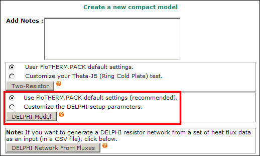
You can add notes to your compact job, if you wish. These notes will be saved with the compact model job you submit.
The DELPHI Model button has two radio choices associated with it. It is recommended that you choose the default Use FloTHERM PACK default settings option, which will directly submit the compact model job.
If you are an experienced user, and want to change some of the compact model parameters, select the Customize the DELPHI Setup Parameters option. This takes you to the DELPHI model setup screen (Figure 6-14).
Figure 6-14.
DELPHI Compact Model Setup Parameters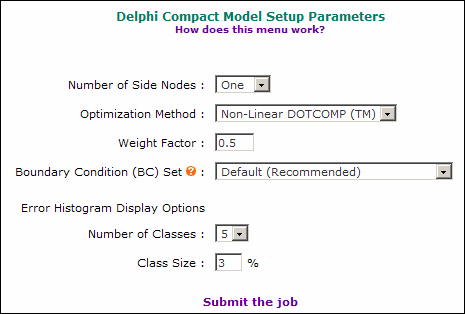
Use this screen to select the type of optimization method, training boundary condition set, and error display options.
- Number of Side and Lead Nodes
In addition to the Top Inner, Top Outer, Bottom Inner, Bottom Outer set of surface nodes, you can also add up to two Side nodes. The default option of one side node is recommended.
Leaded packages (for example; PQFP, PLCC) have the additional option of including more than one lead node (the choice is 1, 2 or 4). Note that choosing 4 lead nodes is likely to greatly increase the time required to generate the compact model, so choose this option only if absolutely necessary.
- Linear Least Squares (LLS). Only the flux term of the objective function is minimized, using classical least-squares method. The LLS method is faster and sometimes more robust, but it is not guaranteed to generate the most accurate compact model possible, as it tends to find a local minima. The top and bottom surface partitioning (each into an Inner and an Outer node) have to be explicitly defined by entering the length (in mm) of the inner nodes for each of the surfaces (see Figure 6-15), the remainder of the area is taken to be the Outer node.
Figure 6-15.
Linear Least Squares Parameters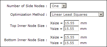
- Non-Linear DOTCOMP™. This method is computationally intensive but almost always yields a compact model with a significantly lower error estimate. The method attempts to find the global minima for the objective function. The Weight Factor (W) represents the relative weighting given to the junction temperature term as compared to the flux term in the cost function. Thus, assigning a value of 1 to W means that only the junction temperature discrepancies are minimized in the objective function, while a value of 0 implies that only the flux terms are taken into account. An intermediate value would indicate the extent to which each of the terms is weighted. The default value is 0.5 (see Figure 6-16), which tends to balance the flux and temperature contributions to the error.
Figure 6-16.
Non-Linear DOTCOMP Parameter
This optimization method also automatically determines the node partitioning of the top and bottom surfaces of the package into the Top Inner/Top Outer and Bottom Inner/Bottom Outer pairs respectively. Therefore, unlike the Linear Least Squares method, there is no need to enter the node areas.
- Boundary Condition (BC) Set
Choose the training boundary condition set used to generate the DELPHI model. If you are not an expert in the theory of the DELPHI methodology it is strongly recommended that you choose the default BC set. Advanced users can use their own BC set and node mapping schemes, see "Customizing Boundary Conditions for DELPHI Model Generation".
- Error Histogram Display Options
This input field refers to the junction temperature error backfit histogram that is displayed once your DELPHI model has been generated. The histogram displays the fraction of the number of BC sets corresponding to each error band. In other words, the errors for junction temperature are grouped in ranges, or classes (in %), and the number of boundary conditions corresponding to each class is displayed.
Submitting the Job
Once you have selected all the options in the DELPHI Compact Model Setup screen, click Submit the Job.
This will submit the job to the job queue and return a message (Figure 6-17) informing you that the job has been submitted.
Figure 6-17.
DELPHI Compact Model Job Submitted
Once a job has been submitted you can monitor its progress as described in “Monitoring the Job Status”.
Examining the Results
The results for compact models can be accessed by clicking on the corresponding icons in the compact model listing. The DELPHI compact model results include a table of the resistor values, a tabulated summary of junction temperature errors, and an error histogram displaying the junction temperature errors (in %), see Figure 6-18.
Figure 6-18.
DELPHI Model Results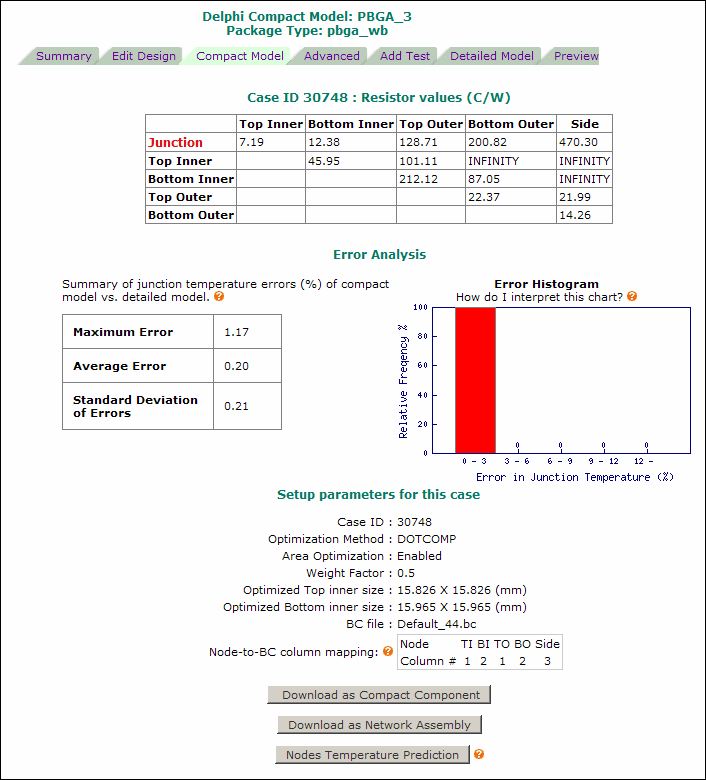
A matrix table of the resistor values (in C/W) makes up the optimized multi-resistor network derived by FloTHERM PACK. The value of any particular resistor, say Junction-to-Bottom-Inner, is found by using the matrix.
Note that the resistor values are presented only as information. You should not modify these values in your compact model after it is imported into FloTHERM.
Once FloTHERM PACK has derived the network from the set training boundary conditions used for the optimization process, it simulates the network under the same boundary conditions and compares the predicted junction temperature with the detailed model results. The results section (just below the resistor matrix) is titled Error Analysis, and contains:
- A summary table of the backfit errors lists the maximum error seen, the average of the absolute values of the errors, and the standard deviation of all the errors.
- A histogram of the errors obtained from the "backfit" of the compact model is also displayed. The histogram displays the fraction of the number of environments corresponding to each error range, or class. In the example shown in Figure 6-18, 100% (that is, all) of the boundary conditions yielded an error in junction temperature (as compared to the detailed model) of less than 3%.
Below the Error Analysis section are two buttons for downloading the DELPHI compact model in PDML format as either a Compact Component SmartPart, or as a Network Assembly. The usage is similar to that for two-resistor compact models, see "Downloading a Two-Resistor Compact Model" and "Two-Resistor Compact Models in FloTHERM".
The Nodes Temperature Prediction button takes you to a “quick-and-dirty” calculator that allows you to predict the junction temperature for your compact network if you know the heat transfer coefficients and ambient temperatures at all the surface nodes, see "The Quick Junction Temperature Predictor Tool".
Notes
- In Version 3.3 all compact models were placed in the default Compact folder. In V4, the Compact folder is no longer used and all compact models are fully integrated with the library to which they belong. Legacy compact models for each user have been assigned to their libraries of origin whenever possible. Those legacy compact models for which original libraries could not be located will still be available in the Compact folder as individual library items, but can be moved or deleted by users.
- After a compact model has been generated, you can change the values in the design sheet. If you do this, the compact model archived in the library will no longer correspond to the part reflected in the design sheet data. If you think you have changed your design sheet data subsequent to the generation of the compact model, click on the Case ID link to recover your design sheet.
- A tick
 under the Notes column indicates the most recently-generated compact model for the particular library.
FloTHERM Compact Component SmartPart
Function
After importing the compact model assembly into FloTHERM, you will see that it includes a FloTHERM Compact Component SmartPart, plus some associated cuboids.
The Compact Component SmartPart is intended to represent network compact models of components. The SmartPart is made up of what appear to be of a number of blocks strung together. The block-like zones within the SmartPart body represent the various nodes of the compact model.
You should really care only about two of the nodes - junction and case, because these are the two temperatures that you will be interested in; be aware that the junction temperature will always be more accurate than the case temperature.
The associated cuboids are separate from the SmartPart, but are a part of the compact model and will be elaborated below.
Structure
The compact model looks a little different in FloTHERM depending on whether your package is leaded (for example, PQFP, TSOP, and so on) or an area array (for example, BGAs).
- Area Array Packages. Refer to Figure 6-19. The assembly contains the SmartPart plus additional cuboids representing the solder balls. The SmartPart contains the various nodes of the network. The center zone represents (one or more) junctions, whereas the top inner node represents the case. There are pre-created monitor points included within the junction and case nodes, so those temperatures can be obtained.
Figure 6-19.
Compact Component SmartPart Structure for Area Array Package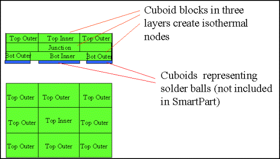
- Leaded Packages. These look very similar to the area array packages (see Figure 6-19), except that the solder ball cuboids do not exist and the SmartPart structure has an additional set of blocks representing the thermal resistance of the external leads.
Figure 6-20.
Compact Component SmartPart Structure for Leaded Package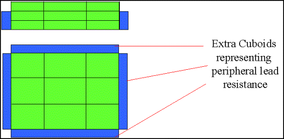
Compact Model Settings
The compact model imported from FloTHERM PACK is intended to be used on an as-is basis, and you should not make any changes in the Compact Component SmartPart menu entries in FloTHERM. If the package parameters are to be changed, you need to return to FloTHERM PACK and re-generate the compact model.
The only exception to this rule is power dissipation of the package if the package has a single die, which may need to be modified. In that case, there is no need to go back to FloTHERM PACK and regenerate the compact model - the adjustment can be done directly in the SmartPart menu itself within FloTHERM. This is possible, because the resistor network derived by FloTHERM PACK is independent of the power of the package as long as the package has only one heat source. To change the junction power:
- Select the Compact Component SmartPart in the FloTHERM Project Manager.
- Right-mouse click and choose Construction.
This brings up the pop-up, partially shown in Figure 6-21.
- Enter a new value for (Junction) Power and click OK.
The new value will be used for the model.
Figure 6-21.
Changing Junction Power in FloTHERM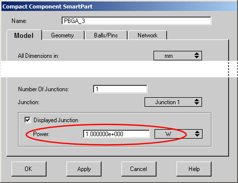
References
- Sarang Shidore and Akbar Sahrapour, DELPHI Compact Models Revolutionize Thermal Design, http://www.flopack.com/Home/article_1.html
- Harvey Rosten et al, Final Report to SEMITHERM XHI on the European-Funded Project DELPHI - the Development of Libraries and Physical Models for an Integrated Design Environment.
- Sarang Shidore and Tom Lee, A Comparative study of the performance of compact model topologies and their implementation in CFD for a Plastic ball grid array package.
- Sarang Shidore, Gary Kromann & Steve Addison, Development of Optimized Component-Level Thermal Behavioral Models of a Plastic-Ball-Grid Array Interconnect Technology For Air Cooled Applications, Proceedings of InterPACK ’97 Conference, June 1997, Hawai’i, U.S.A.
- W. Temmerman et al, Experimental Validation Methods for Thermal Models.
- JEDEC Standard, High Effective Thermal Conductivity Test Board for Leaded Surface Mount Packages, JESD 51-7, https://www.jedec.org
- DELPHI Compact Model Guideline, under standardization process by JEDEC, https://www.jedec.org
