Customizing Boundary Conditions for DELPHI Model Generation
Theoretical Background
A detailed description of the DELPHI compact model generation process in FloTHERM PACK is given under "DELPHI Compact Models in FloTHERM PACK". Some of the key aspects of the process are listed below:
- The detailed model used for generating the compact model is the one that would be consistent with the modeling choices selected by the user in the Modeling Choices section of the design sheet. In other words, changing these choices in the design sheet changes the compact model, such that the network is always derived from the selected detailed model.
- Two optimization techniques are offered: the more traditional Linear Least Squares (LLS) method, and a state-of-the-art non-linear DOTCOMP™ method. The LLS method is faster and sometimes more robust, but it is not guaranteed to generate the most accurate compact model possible. The DOTCOMP method is computationally intensive but almost always yields a compact model with a significantly lower error estimate.
A DELPHI compact model must be derived using an optimization process over a “universal” boundary condition set, defined as the “training” set. Such a set should reflect the full spectrum of typical environmental conditions encountered by the package electronics applications. The DELPHI consortium proposed a set of 38 such boundary conditions, known as the 38-set, which was later expanded to the 99-set. Since then, other sets have been proposed in the literature. FloTHERM PACK uses a version of the most recent proposals.
The boundary condition sets are typically presented as a matrix containing heat transfer coefficients (h.t.c.’s). Each row corresponds to one boundary condition scenario. Each column represents a particular class of boundary conditions. Each row represents a single simulation, whereas each column (class) represents specific areas on the package surface on which the h.t.c.’s are applied. Thus, the column labelled “Top” in Figure 6-29 is a set of h.t.c’s that represent conditions typically encountered at the top surface of a package, ranging from free to forced convection, and with and without a heatsink. A similar concept applies to the other classes.
Often the training set is further broken down into environment categories, which represent typical operating environments, for example, forced convection, natural convection, attached heatsink, and so on. Thus, the boundary condition rows can be further classified into environment categories. The 38-set proposed by the original DELPHI consortium is shown in Figure 6-29.
Figure 6-29.
Proposed 38 Boundary Condition Set for a Leaded Package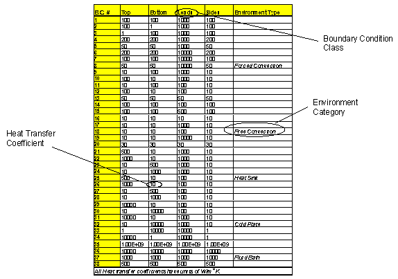
The training boundary condition set may be a function of the package style in question. Two fundamental categories of packages can be distinguished - area array and leaded packages. Area array packages allow for two principal directions of heat transfer (top and bottom) whereas three principal directions need to be analyzed for leaded packages (top, bottom, and leads). The training boundary condition set could differ for these two package styles.
Creating Your Own Boundary Condition Sets
The boundary condition sets used in FloTHERM PACK V5.1 and above are the 44-set for area array packages, and the 44X2-set for leaded packages. The 44-set is a condensed version of the 99-set. The 44X2-set is the 44-set with additional rows generated by interpolation. The broader set was found to be necessary for leaded packages, which potentially have several more surface nodes than area array packages.
In FloTHERM PACK V5.1 and above, you can define your own custom boundary condition sets in CSV files and upload them into your designs.
BC CSV File Format
The contents of the CSV file must be in a specific format, refer to Figure 6-30, which shows the first four boundary conditions of a 44-set. You can add comment lines at the top of the file, but if you do, these must start with the # character.
Figure 6-30.
Sample Boundary Condition (CSV) File Ready for Upload

The data comprises a number of rows, N, each representing one boundary condition scenario or single simulation.
The data in each row is made up of a number, M, of heat transfer coefficient values (in W/m2K) separated by commas.
It is perhaps easiest to think of the data in the CSV file as being made up of N scenarios and M classes. A class representing a specific area on the package surface on which the heat transfer coefficients are applied. Thus, one column may be a set of heat transfer coefficients that represent conditions typically encountered at the top surface of a package - ranging from free to forced convection, and with and without a heatsink. A similar concept applies to the other classes.
How you arrange your columns is up to you but they must be consistent. The last part of the process allows you to map your columns to surface nodes of the compact model, see "Mapping a Boundary Condition Set to Nodes".
Uploading Your File
- Select the Customize the DELPHI setup parameters radio button option before clicking DELPHI Model when creating a new DELPHI model (Figure 6-31).
Figure 6-31.
Customizing a DELPHI Model
This takes you to the DELPHI Compact Model Setup Parameters screen.
Figure 6-32.
User-Defined BC Option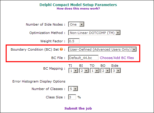
- The Boundary Condition (BC) Set drop-down list has two options. Select User-Defined (Advanced Users Only). (The other option is the default and recommended for non-expert users, see "The DELPHI Model Setup Screen".)
This brings up a field which names the current BC File, (Default_44.bc in the example shown in Figure 6-32).
- Click the adjacent Choose/Add BC Files link.
This brings up a pop-up window (Figure 6-33) that lists the default boundary condition sets:
- Default_44 for area array packages (file Default_44.bc)
- Default_44X2 for leaded packages (file Default_44X2.bc)
- Click Add a new BC file to create a new boundary condition set.
- This Upload BC file pop-up window is displayed, which allows you to specify and upload a BC set in CSV format.
- Click Browse to locate and select your CSV file, then click Load (Figure 6-34).
Figure 6-34.
Uploading a BC (CSV) File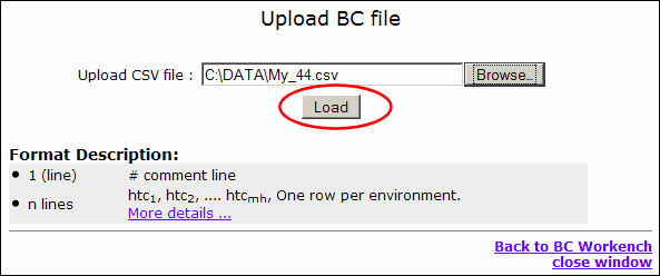
A pop-up window shows the details of the contents of the file, see Figure 6-35. Note that this window can be recalled at any time by clicking on the File Name link in the list of BC files (Figure 6-36).
Figure 6-35.
Uploaded File Data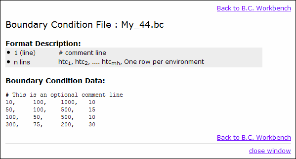
By convention, the filename is given a “.bc” extension. You can give the file any extension name prior to uploading but it will be stored on the system as a *.bc file. A *.csv file is renamed as *.bc, but files with other extension names have the extension name carried into the filename, for example file.txt becomes file_txt.bc.
- Click Back to B.C. Workbench
You are taken back to the list of boundary condition files. The uploaded file is added to the standard default list as a user defined file, see Figure 6-36.
Figure 6-36.
Default and Uploaded BC Files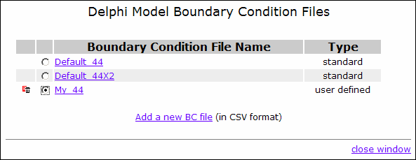
- To use the uploaded BC file, select the corresponding radio button.
You are taken back to the DELPHI Compact Model Setup Parameters screen. For the next step, see Mapping a Boundary Condition Set to Nodes.
Mapping a Boundary Condition Set to Nodes
Having uploaded and selected a boundary condition set, use the DELPHI Compact Model Setup Parameters screen (Figure 6-37) to map columns in your BC file to the appropriate surface nodes of the compact model (or more accurately, the surface node partitioning of the detailed model).
The surface nodes (TI, BI, TO, BO, Side (and Lside<n> in the case of leaded packages)) have drop-down selections corresponding to the number of columns in your CSV file (refer to "BC CSV File Format"). In the example shown there were four columns and therefore the drop-down choice is from 1-to-4. In Figure 6-37 the data in the first column of the CSV file has been mapped to the Top Inner node, the data in the second column has been mapped to the Bottom Inner node, and the mapping of the Top Outer node is about to be selected.
Figure 6-37.
BC Mapping to Nodes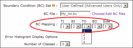
References
- JEDEC standard, DELPHI Compact Model Guideline, to be published, https://www.jedec.org
- Sarang Shidore, Gary Kromann & Steve Addison, Development of Optimized Component-Level Thermal Behavioral Models of a Plastic-Ball-Grid Array Interconnect Technology For Air Cooled Applications, Proceedings of InterPACK ’97 Conference, June 1997, Hawai’i, U.S.A.
