The Library Menu
What were termed as designs in V3 and earlier releases, are now called libraries. The change of term reflects the fact that the design or design sheet is now only a subset of a more expanded data definition constituting the part.
To generate a new library, click on New Library on the top menu bar of your workbench. This link brings up a drop-down list of all the libraries supported, categorized by class and type of library. To help you in mapping your actual part to the library classification, a visual image is provided when each choice is displayed.
Once the library is generated, in most cases with the aid of the SmartPart Wizard, it appears as an item in your default folder in the workbench.
Clicking on a specific library item in your workbench leads you directly to the Summary display of the library. This is a change from V3, when the only display available was the design sheet. In V4, you will see a number of tabs on the top of the display for a given library that will take you to various sub-menus, as explained below.
Summary Tab
The Summary display is a major new feature of V4 over earlier versions. This display shows high level library data, called metadata.
Figure 2-2.
Summary Sheet of IC Component Library with Minimum Data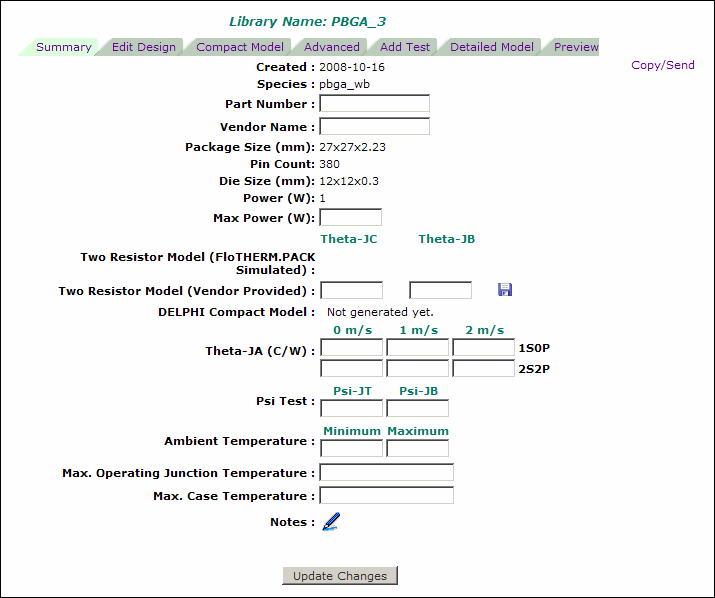
Some of this metadata (such as part size, power, and die size) is extracted directly from the design sheet (see Edit Design below), but much of it (such as Theta-JA, Maximum allowed case and junction temperatures, part numbers, vendor name, etc.) is data about the library above and beyond that strictly required for the generation of thermal models, and is to be filled in by you as needed. Some of this metadata can also be displayed in the main workbench display by setting appropriate User Preferences, and thus is searchable with The Search Options feature.
You can add notes to your library. The notes section can be edited by clicking on the pencil icon  located at the end of the summary sheet. The workbench display shows only the first 120 characters of the notes field.
Figure 2-3.
Summary Sheet of IC Component Library with All Data Filled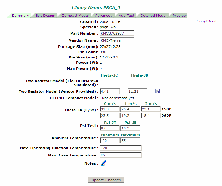
Edit Design Tab
Clicking this tab will display the design sheet of the library. The design sheet contains all the lower level data that constitutes the geometric and material definition of the library. It also contains the modeling options for generating a thermal detailed model.
Figure 2-4.
Editing Your Design Sheet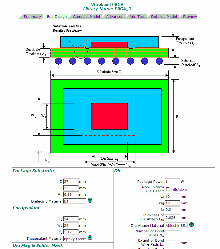
In FloTHERM PACK V4 and above, localized grid is supported. Within the modeling options of a design sheet you are given a choice of attaching a localized grid constraint. This constraint will be attached to the detailed model.
The lowest grid density option is the keypointed grid only. The medium and high grid density options add more grid to the detailed model. Make sure you check the localized grid box for these choices to take effect.
Figure 2-5.
Localized Gridding Options for Library
Please consult your FloTHERM on-line help section for general information about localized gridding.
Compact Model Tab
Compact models are abstracted but more efficient thermal representations of an IC component that attempt to predict the junction and case temperatures of the component with a significantly reduced computational cost. These are typically in the form of thermal resistor networks. FloTHERM PACK generates two types of compact models, two-resistor (see “Two-Resistor Compact Models”) and DELPHI (see “DELPHI Compact Models”).
This tab displays the compact models generated from this library. Icons indicate whether the model is a two-resistor or a DELPHI type. Clicking these icons allows you to see the data constituting the compact model, and an error bar chart (in case of DELPHI compact models only).
Figure 2-6.
List of Compact Models Available for Library Item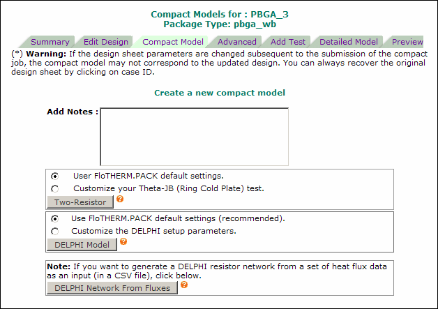
To submit a compact model job go to the Compact Model tab and click the button for either Two-Resistor or DELPHI Model. You can add notes to your compact case. In the case of two-resistor compact models, you can also modify the test board that FloTHERM PACK will use in a Theta-JB simulation.
Monitoring the Job Status
Typically, your job will finish in a few minutes, but the time will depend on the load on the server. On completion, you will be notified by an email, sent to the email address specified in Preferences > Account Information.
Once a job is submitted, the job status can be monitored in the compact model job queue by clicking the job queue link, see Figure 2-7.
Figure 2-7.
Model Job Submitted
You can check the job status by re-clicking the Compact Model tab in your library, which will list all pending and completed jobs. A color code indicates job status:
- Red = Case in queue. For example, see Figure 2-8.
- Blue = Case in progress, or case picked up for solving. For example, see Figure 2-9.
- Green = Case completed but results not viewed. For example, see Figure 2-10.
- White/Off-White = Case completed and results have been viewed. For example, see Figure 2-13.
Figure 2-8.
DELPHI Compact Model Job in Queue
Figure 2-9.
DELPHI Compact Model Job In Progress
Figure 2-10.
DELPHI Compact Model Job Finished
Viewing the Results
The results for the two-resistor and DELPHI compact models can be accessed by clicking on the corresponding Model Type icon in the compact model listing. Two-resistor compact models are denoted by the  symbol, DELPHI compact models are denoted by the
  symbol.
The two-resistor results are the resistor values for Theta-JC and Theta-JB (or Rjc and Rjb), see Figure 2-11.
Figure 2-11.
Two-Resistor Model Results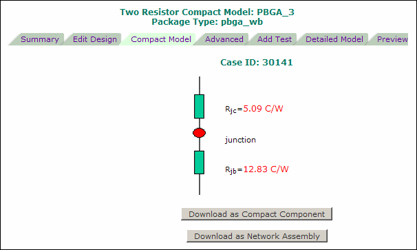
The DELPHI compact model results include a table of the resistor values, a summary of % errors, and an error analysis histogram, see Figure 2-12.
Figure 2-12.
DELPHI Model Results showing Resistor Table and Error Histogram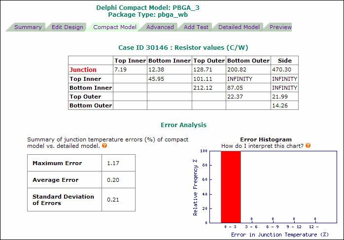
Notes
- In Version 3.3 all compact models were placed in the default Compact folder. In V4, the Compact folder is no longer used and all compact models are fully integrated with the library to which they belong. Legacy compact models for each user have been assigned to their libraries of origin whenever possible. Those legacy compact models for which original libraries could not be located will still be available in the Compact folder as individual library items, but can be moved or deleted by users.
- After a compact model has been generated, you can change the values in the design sheet. If you do this, the compact model archived in the library will no longer correspond to the part reflected in the design sheet data. If you think you have changed your design sheet data subsequent to the generation of the compact model, click on the Case ID link to recover your design sheet.
- A tick
 under the Notes column indicates the most recently-generated compact model for the particular library.
After you have viewed the results of a generated compact model it will appear in the listing as white or off-white, for example, see Figure 2-13.
Figure 2-13.
Compact Models Listing
Advanced Tab
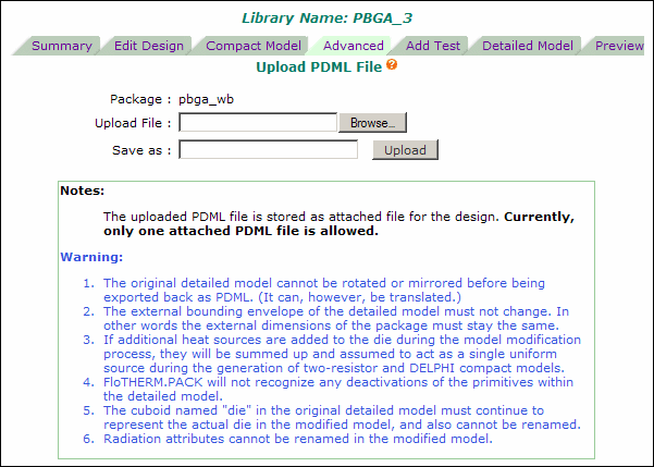
You can download a detailed model of an IC component from FloTHERM PACK (as described under "Detailed Model Tab"), modify the geometry, power, or materials in FloTHERM (within the restrictions as described under Detailed Model Tab), export as a PDML file, and then upload this modified package model to the library within FloTHERM PACK. The modified PDML file is then available for generating a two-resistor compact model.
To upload a PDML file, click the Advanced tab (Figure 2-14).
Click the Browse button to locate the PDML file on your hard drive, and then the Upload button to upload it to FloTHERM PACK. You will also have to specify a name for this attached file, which can be different from the original name. FloTHERM PACK will then upload your PDML file and associate it with the particular library.
Add Test Tab
If the library in question is an IC component, then FloTHERM PACK allows you to add a test board and a standard JEDEC test environment (for example, 2S2P test board in a Still Air environment) directly from within the library display. The output will be a ready-to-solve PDML file that can be imported into FloTHERM. All you then need to do is to click Solve within FloTHERM and wait for the solution to converge.
To add a standard test board and environment to the library, click the Add Test tab and follow the instructions. (Note that this tab is not available for any library that is not an IC component.) For more details, see “Standard JEDEC Test Models”.
Detailed Model Tab
You can download a detailed model of an IC component from FloTHERM PACK, modify the geometry, power, or materials in FloTHERM, export as a PDML file, and then upload this modified package model to the library within FloTHERM PACK (see Advanced Tab).
Note: The following restrictions apply when modifying detailed models if they are to be successfully uploaded back to FloTHERM PACK.
- The external dimensions of the package must remain the same as those of the original package.
- There must be a cuboid named “die”.
- There must be a source named “DieSource” having a source value greater than zero. If there are additional heat sources, they will be summed up and assumed to act as a single uniform source during the generation of two-resistor and DELPHI compact models.
- There must be a monitor point named “DieJunction_Temp” and one named “CaseTemp”.
- There cannot be any primitives such as Compact Component, Heat Sink, Network Assembly, Heat Pipe, Fan, and so on, in the detailed model.
The modified PDML file is then available for generating a two-resistor compact model.
To download a PDML file, click the Detailed Model tab, see Figure 2-15.
Figure 2-15.
Downloading a PDML File of a Modified Detailed Model
A pop-up dialog (Figure 2-16) allows you to either open the PDML in FloTHERM, provided you have a copy of FloTHERM, or save the file to a folder of your choice.
Figure 2-16.
Open or Save a PDML File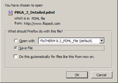
Library Preview Tab
You can view you library as a 3-dimensional image, provided you have an installed VRML viewer on your computer. Most viewers allow panning, rotating, and zooming the view. VRML viewers can be found on the internet; a useful list is at:
www.web3d.org/x3d-resources/content/examples/X3dResources.html
Provided you have associated WRL files with your viewer, you can launch the viewer and display the library by clicking the Preview tab. A pop-up dialog (similar to that shown in Figure 2-16) allows you to either open the WRL file, or save it to a folder of your choice.
