Solder Balls
Introduction
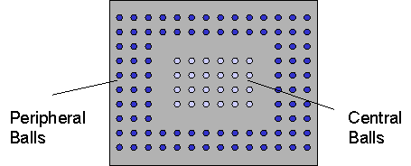
Solder balls are typically made of 95Pb/5Sn or 37Pb/63Sn. The solder ball array can be peripheral, with additional central balls, see Figure 4-19.
Figure 4-19.
Solder Ball Array
The central balls are often "thermal" balls, that is, their sole function is strictly heat removal.
General Thermal Considerations
In most packages with solder balls, a substantial portion of the heat from the package flows to the board through the balls. This is true even if the package has a heatsink present. Therefore modeling solder balls accurately is important.
The solder balls represent a good conduction path to the board. The air gaps between them, however, act practically as insulators. This means that heat flux lines "crowd" in and out as they flow from the package substrate to the board. This effect can sometimes be significant, especially when the number of solder balls is small, and/or the substrate or the board conductivity is relatively low.
Modeling Options
The following techniques exist for modeling solder balls:
- Discretely, using non-collapsed cuboids
- Lumped, using collapsed cuboids
- Lumped, using non-collapsed cuboids
Discrete
This is the most preferred approach. It takes into account heat flux "crowding" effects, as it is the most physically accurate representation. It is advisable for packages with a relatively small number of solder balls, or when the package substrate is significantly non-isothermal (for example, Organic Substrates). The disadvantage of this method is the large computational time required.
Because the cross-section of an actual solder ball is circular, FloTHERM PACK represents this as an equivalent square area, see Figure 4-20 and Figure 4-21.
Figure 4-20.
Actual Solder Ball Cross-Section
Figure 4-21.
Representation of Solder Ball Cross-Section
Lumped, with Collapsed Cuboids
In order to save grid count, it is possible to represent a contiguous ball array by a single collapsed cuboid. The equivalent conductivity of the collapsed cuboid is obtained by volume averaging the solder and air conductivities, see Figure 4-22 and Figure 4-23.
Figure 4-22.
Actual Solder Balls
Figure 4-23.
Collapsed Cuboid Option
The disadvantages of this method include an inability to capture heat flux crowding effects, and a loss in the model height (profile) that is result of having a zero physical thickness for the solder ball layer.
Lumped, with Isotropic Full Cuboids
Another method to represent a contiguous solder ball array is by the means of a single full cuboid. This method has the advantage of preserving the profile (height) of the package. However, FloTHERM PACK will generate a cuboid which is isotropic, that is, has the volume averaged conductivity in all directions. In fact, the air gaps between the individual solder balls ensure that the lateral heat transfer is negligible in the array. Hence, the cuboid representation will introduce a spurious spreading that does not exist, resulting in a lower junction temperature than that in reality.
Figure 4-24.
Representation with Full Cuboid
Due to the inaccuracies of the isotropic assumption users are advised to avoid using this option and instead choose the option of lumped cuboid with orthotropic conductivity (see below).
Figure 4-25.
Spurious Lateral Spreading in Isotropic Cuboid
Lumped, with Orthotropic Full Cuboids
The spurious spreading effect is avoided if this option is chosen, as FloTHERM PACK sets the conductivity in the in-plane directions to that of air (0.026 W/(m.K)), while using the volume averaged value for the normal direction. The resultant model is expected to be more accurate than the collapsed isotropic cuboid representation (although still less accurate than the discrete balls model).
Material Properties
37Pb/63Sn solder: 50.6 W/(m.K)
95Pb/5Sn solder: 35.5 W/(m.K)
Validation & References
- Pavel Valenta, Thermal Modeling of Ball Grid Arrays, 5th International FloTHERM User Conference, 1996, Paris, France.
- Sarang Shidore and Tien-Yu Tom Lee, A Comparative Study of the Performance of Compact Model Topologies and their Implementation in CFD for a Plastic Ball Grid Array Package, Proceedings of InterPACK ’99 Conference, June, 1999, Hawai’i, U.S.A.