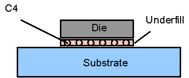
C4 Interconnect
Introduction
- Interconnection technology that connects a Die directly to the substrate by means of solder bumps
- Solder balls usually not in regular array
- Typical diameter ~ 3 mils
- Common solders used: 95Pb/5Sn, 37Pb/63Sn
General Thermal Considerations
- Usually have a small, but significant thermal resistance (especially for ceramic packages)
- Negligible heat spreading in C4 layer
Modeling Options
FloTHERM PACK represents the C4 interconnection as a collapsed cuboid. It is not necessary to represent it as a full cuboid due to the negligible spreading effect it causes. If the die is modeled as a constant heat flux source, then modeling the solder bumps discretely is not advisable due to the excessive grid generated, and the negligible improvement in results.
Figure 4-31.
Representation of a C4 Interconnect
Material Properties
97Pb/3Sn solder: 33 W/(m.K)
Validation & References
- Gary Kromann, Thermal Management of a C4/Ceramic-Ball-Grid-Array: The Motorola PowerPC 603 and 604 RISC Microprocessors, Proceedings of SEMITHERM, 1996.
- Tien-Yu Tom Lee, & Mali Mahalingam, Thermal limits of flip chip package-experimentally validated, CFD supported case studies, Proceedings of the Fourth International FloTHERM User Conference, October 1995, San Jose, U.S.A.
